In the execution details, injections of cement and chemical mixtures were first made to consolidate the excavation fronts and make the ground more homogeneous in view of freezing. Subsequently, freezing probes and thermometric probes were positioned, with an average length of about 40 m, arranged to form a wall of frozen soil thick enough to guarantee structural support and waterproofing during the subsequent excavation phases. The probes were arranged in such a way as to leave the last meter of soil below the existing slab not frozen, so as to allow this layer to be free to deform to absorb any uplifts due to the formation of the ice wall. On the sides of the screen of frozen soil, given the presence of permeable materials in contact with the existing line A station, it was decided to install additional freezing pipes from which to execute, if necessary, a controlled waterproofing freezing (“soft ice”). In order to further contain any deformations induced by the formation of the ice wall, it was also decided to install deformable pipes in the area between the ice front of the uprights and the existing slab and “magrone”.
Consolidation and waterproofing schemes of the tunnels using freezing probes
Consolidation and waterproofing schemes of the tunnels using freezing probes
Once the ice wall was formed, the cutting of the walls of Line C and Line A was proceeded, the traditional tunnel excavation, with the laying of a temporary lining made of metal ribs and sprayed concrete, and finally the excavation of the lowered arch, with waterproofing and casting of the final lining.
Once the final lining of the undercrossing tunnels was completed, the re-profiling of the existing Line A station foundation piles, interfering with the passage sections of the new Line C trains, was carried out.
To allow the arrival of the Mini-tunnels near the walls of the existing Line A station on the T3 side, once the undercrossing tunnels have been completed, a further consolidation intervention is also planned, using cement and chemical injections. The intervention, carried out directly from the front of the same tunnels, aims to create a protective shell within which the disassembly of the milling heads of the Mini-tunnels can proceed.
The project has had an exceptional technical value due to the constraints dictated by the pre-existing structures, in particular the foundation piles of line A which imposed interaxes between the freezing pipes of over 3 and a half meters and for the complex stratigraphic and hydraulic conditions present on site.
Therefore, freezing modifies the thermal properties of the soil as well as those of resistance. The correct determination of the thermal characteristics is therefore fundamental for a more reliable prediction of the freezing time, power, and refrigerating capacity necessary to obtain the required design requirements.
The particular complexity of the project required the use of a mixed 2-phase freezing system.
In the first phase of freezing, a “liquid nitrogen” freezing was used, also called “open cycle” or “direct” (figure 5); the refrigerant fluid (compressed gas in the liquid state with a temperature of -196°C) circulates in an open circuit and, after passing through the freezing probes, is dispersed in the atmosphere in a gaseous state. This allowed to reduce the execution times and to obtain at the same time a greater security of closure of the ice wall in correspondence of the line A piles, where the interaxes between the freezing pipes reached measurements of over 3.5 meters.
In the second phase of tunnel construction, the frozen wall was maintained using refrigeration units and “brine” as a refrigerant, an aqueous solution of calcium chloride with a freezing point between -40 °C and -50 °C. This freezing system is also called “closed cycle” or “indirect”; the refrigerant fluid, after its passage through the freezing probes, where it exchanges heat and heats up, returns to the refrigeration plant, is cooled again and from there sent back to the freezing probes.
This allowed a greater control of the evolution over time of the ice wall, allowing to limit the deformations induced on the existing slab of Line A.
Site Logistics and Minimization of Impact on the Population
The position of the site in the centre of the city, the limited space and the simultaneous congestion of activities, required complex design solutions especially regarding the realisation of the distribution plant of the refrigerant fluids, liquid nitrogen and brine.
Industrial refrigeration plants with ecological refrigerants were used, carefully controlled and subject to periodic inspection checks.
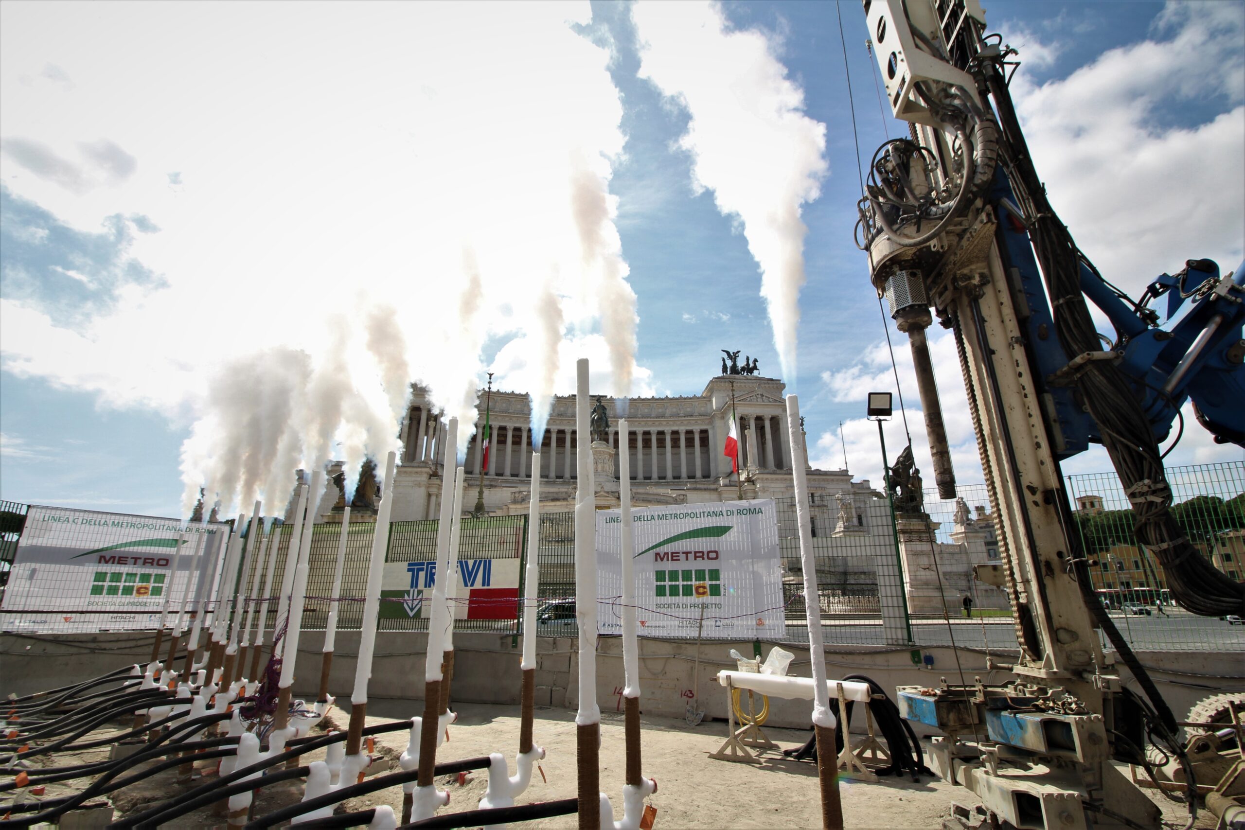
Particular attention was paid to the issues of emissions into the atmosphere and minimization of the visual impact of exhaust fumes on residents of the neighbourhood.
As far as industrial refrigeration plants are concerned, evaporative type condensers and cooling towers that use water/air heat exchanges were adopted. At the tower exit, the flow of air, hot and saturated with moisture, undergoes a sudden cooling, part of the contained water condenses generating only a white plume of water vapor.
As for the liquid nitrogen freezing system, the latter, at the exit from the freezing probes is dispersed in a gaseous state in the atmosphere at a temperature variable between about -60 °C and -120 °C.
Nitrogen is a non-toxic, odourless, colourless and non-flammable gas, present in the atmosphere at 78%. The condensation that forms on contact with the air manifests itself in white smoke. Its emission in open environments poses no health risk.
Monitoring Systems
The complexity and importance of the work required the use of various monitoring systems, aimed at both safeguarding the safety of operators and controlling existing structures and freezing activities.
Monitoring system of the percentage of oxygen present in the air
A monitoring system for the percentage of oxygen present in the air has been installed to safeguard the workers who work underground in the presence of freezing probes powered by liquid nitrogen.
When the alarm threshold is reached, the system automatically closes the nitrogen delivery solenoid valve and triggers an alarm that allows to identify the gas leak as quickly as possible and at the same time makes it possible to evacuate the operators.
Structural monitoring
An integrated monitoring system allows the control of existing structures.
The system is composed of:
– Leveling cups indicate any induced deformations on the foundation slab of line A station;
– Thermometers inserted inside the slab, signal the approach of the front of frozen ground to the underside of the same;
– Miniprisms and topographic benchmarks control the deformations of the load-bearing structures of San Giovanni station line “A”, diaphragms, piles, slabs, etc.
– Electrolevels monitor any deformations of the metal bridges
Monitoring of ground temperatures
A special monitoring system allows the control and management in “real time” of the process of ground freezing and the subsequent maintenance of the ice wall. The control of temperatures is carried out by thermometric probes, consisting of a series of sensors, positioned on the contour of the ice wall at known and measured distances.
The understanding of the temperature trend as a function of time and distance with respect to the freezing probes, allows to monitor the evolutionary state of the ice wall; once the project conditions have been reached, in terms of continuity and closure of the ice wall, thicknesses and temperatures, it is possible to proceed with the excavation of the tunnels.
Conclusions
The undercrossing project of the San Giovanni Station Line A has had exceptional technical value due to the constraints dictated by the pre-existing structures and the complex stratigraphic and hydraulic conditions present on site. The experience gained will serve as a useful reference for other future applications of the artificial ground freezing methodology in stratigraphic, geotechnical, and environmental contexts of a similar nature.