On August 29, 2020, the tunnel excavation activities using Tunnel Boring Machines (TBMs) for Metro C, in the section between San Giovanni Station and Piazza Venezia, were completed. Since September of that year, the dismantling of the two machines and their related equipment has been in progress.
These two TBMs had previously been used, until 2011, to construct the tunnels in the T4 section (from Via dell’Acqua Bulicante to Largo Brindisi – San Giovanni). After completing the excavation of the T4 section, they were disassembled, underwent maintenance, and were then reassembled at the Via Sannio Shaft, through which they were brought back to the excavation level.
Between March 2018 and August 2020, they constructed the tunnels for the T3 section, initially reaching Via dei Fori Imperiali and later, following a design modification at the end of 2019, extending to Piazza Venezia.
TBM Details and Composition:
The two Tunnel Boring Machines (TBMs) used for the construction of the T3 section tunnels are of German production, specifically EPB (Earth Pressure Balance) technology manufactured by Herrenknecht. They can be described as cylindrical in shape, with a diameter of approximately 6.70 meters and a length of around 11 meters. These TBMs are accompanied by a convoy of 7 carriages (back up) containing all the necessary equipment for their operation, resulting in an overall length of about 95 meters.
They mainly consist of:
- A milling head containing the excavation tools and suitable openings for introducing soil into the rear excavation chamber;
- A cylindrical metal “shield,” which includes:
- A “front shield” housing the “main drive,” the main bearing of the machine responsible for rotating the milling head, along with its gear motors and the rotary joint for injecting materials needed to condition the soil in the excavation chamber;
- A “rear shield” containing systems for advancing the machine in the soil and for assembling the tunnel lining;
- A “tail” inside which the final tunnel lining is installed, consisting of reinforced concrete segments (rings).
- A convoy of 7 back-up carriages, mainly containing the following equipment:
- Carriage 1 contains the control cabin, pumps for injecting the two-component grout for backfilling behind the rings (with related tanks, control panels, and command units);
- Carriage 2 contains the sliding beams of the “gantry” (the structure for transferring the rings inside the shield); it also contains hydraulic pumps for the machine’s operation and pumps for injecting sealing grease for the tail brushes and oil and grease for various circuits. Additionally, it includes electric motors for thrusting forward and a heat exchanger for circuit cooling;
- Carriage 3 contains the aforementioned ring transfer gantry and electrical control panels for the machine’s operation;
- Carriages 4, 5, 6, and 7 contain further components necessary for the machine’s operation (particularly the cable reel for Medium Voltage cable with its respective transformer, elements of the cooling circuit, and compressed air for the machine, as well as hose reels for water, air, and cement grout).
The shields and the tail are connected by cylinder systems that allow reciprocal movements necessary to accommodate the curves in the tunnel construction route.
The end part of the tail is equipped with systems (“brushes”) that prevent the inflow of water contained in the soil and cement grout injected by the TBM behind the tunnel lining during excavation or while the TBM is in the ground. This is done to prevent soil collapse.
Phases of TBM disassembly
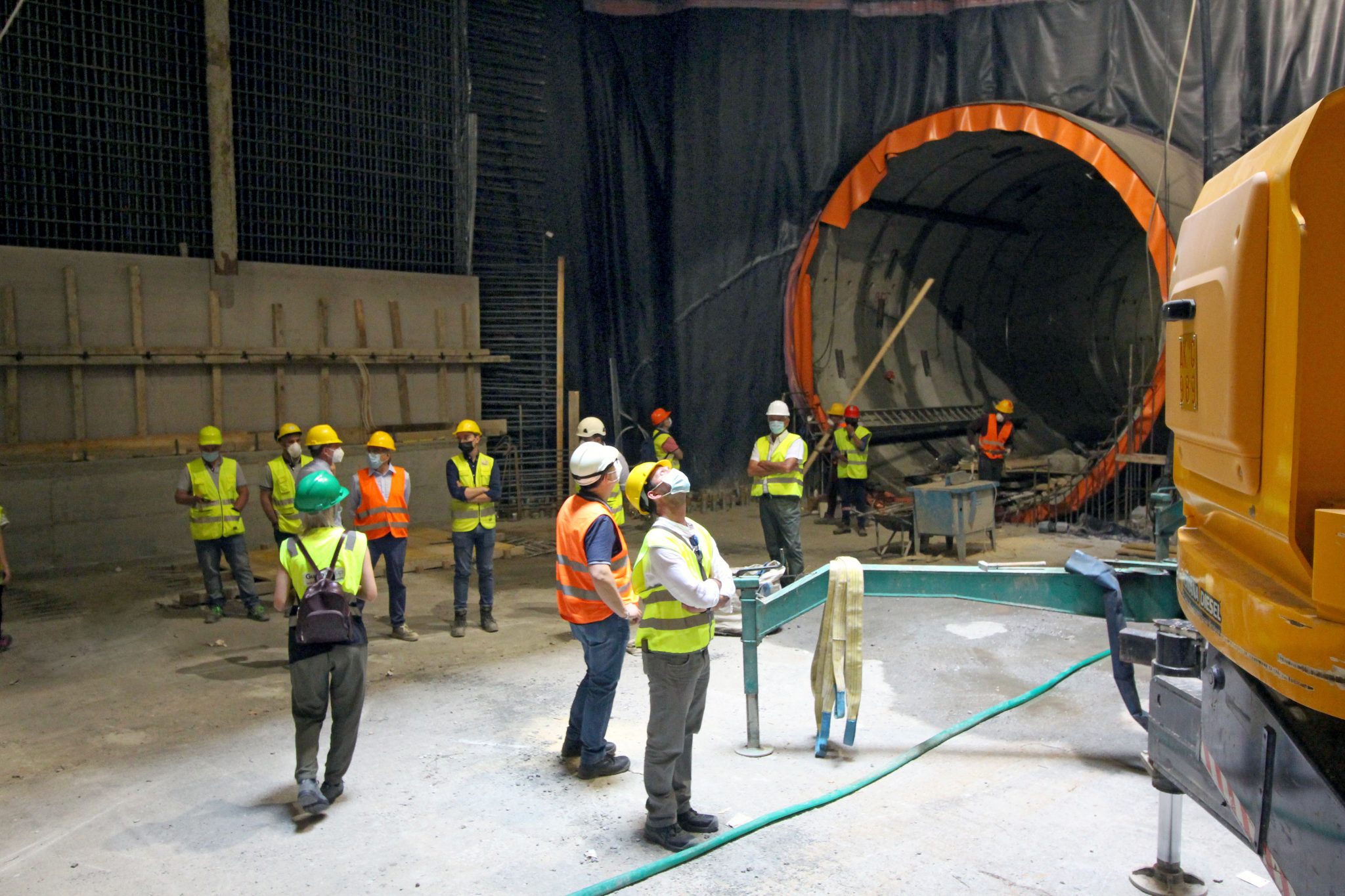
It is planned that the shields of the two machines will be left in the ground after securing them by filling the excavation chamber with cement grout and creating a reinforced concrete “liner” inside the cylindrical shield. They will be recovered later when the perimeter box of the “Venezia” station is constructed.
This is done to avoid any long-term structural collapse of the TBMs or the entry of materials inside the machines.
At the end of excavation, to allow the completion of work in the structures (stations and shafts) affected by the passage of the machines, as well as the installation of all necessary equipment (railway tracks and associated technological systems) in the tunnels they have excavated, a complete dismantling of all equipment and systems required for the operation of the TBMs is carried out.
At the end of the excavation, in order to allow the completion of work in the structures (stations and shafts) affected by the passage of the machines, as well as the construction of all the necessary systems (railway tracks and associated technological systems) in the tunnels excavated by the TBMs, a complete dismantling of all equipment and systems required for the operation of the TBMs is carried out.
In particular, at the Amba Aradam Station, which was used as a logistical base for the mechanical tunnel excavation due to its location and logistical configuration, the systems for managing the excavation material conveyors and all the necessary feeding systems for tunnel construction are dismantled.
Simultaneously with the dismantling of the tunnels, the seven backup cars that contain all the equipment and technologies necessary for the operation of each TBM are also removed.
Finally, to proceed with the construction of the reinforced concrete lining inside the shield of the machines, the main components (screw conveyor, erector with its bridge and H-beam, thrust cylinders and articulation, hyperbaric chamber and passage devices, rotary joint, and main drive gearmotors) are removed from them.
Final Workings
The dismantling of the equipment serving the TBM machines inside the tunnels and at the logistics site of the future Amba Aradam Station has been completed.
The backup cars of the two TBMs have been disconnected and removed.
All equipment and systems inside the TBM shield on the even track have been removed, and a reinforced concrete lining has been installed inside it (similar activities are in the final stages for the TBM on the odd track).


